UNITED STATES PATENT OFFICE.
THOMAS A. EDISON, OF NEWARK, NEW JERSEY.
IMPROVEMENT IN AUTOGRAPHIC PRINTING.
Specification forming part of Letters Patent No. 180,857,
dated August 8, 1876; application filed March 13, 1876.
To all whom it may concern:
Be it known that I, THOMAS A. EDISON, of Newark, in the county of Essex and State of New Jersey, have invented an Improvement in Autographic Printing, of which the following is a specification:
Patterns for embroidery and for fresco painters have been made of paper, perforated with numerous holes in the lines to be transferred, and the transfer has been done by a fine colored powder, dusted over and rubbed into such holes while the article is upon the surface that receives such transfer. This is not adapted to writing, because the color employed is not permanent, and no means has been devised that could easily be made use of in writing or drawing by hand with rapidity that rendered the operation practically available for autographic printing.
My improvement relates, first, to the instrument employed for puncturing the paper, whereby such instrument can be used by hand in the same manner as a drawing or writing pen; second, to the method of printing by direct transfer in permanent semi-liquid ink from the perforated sheet; and third, to the press for holding such transfer-sheet, and the paper to be impressed.
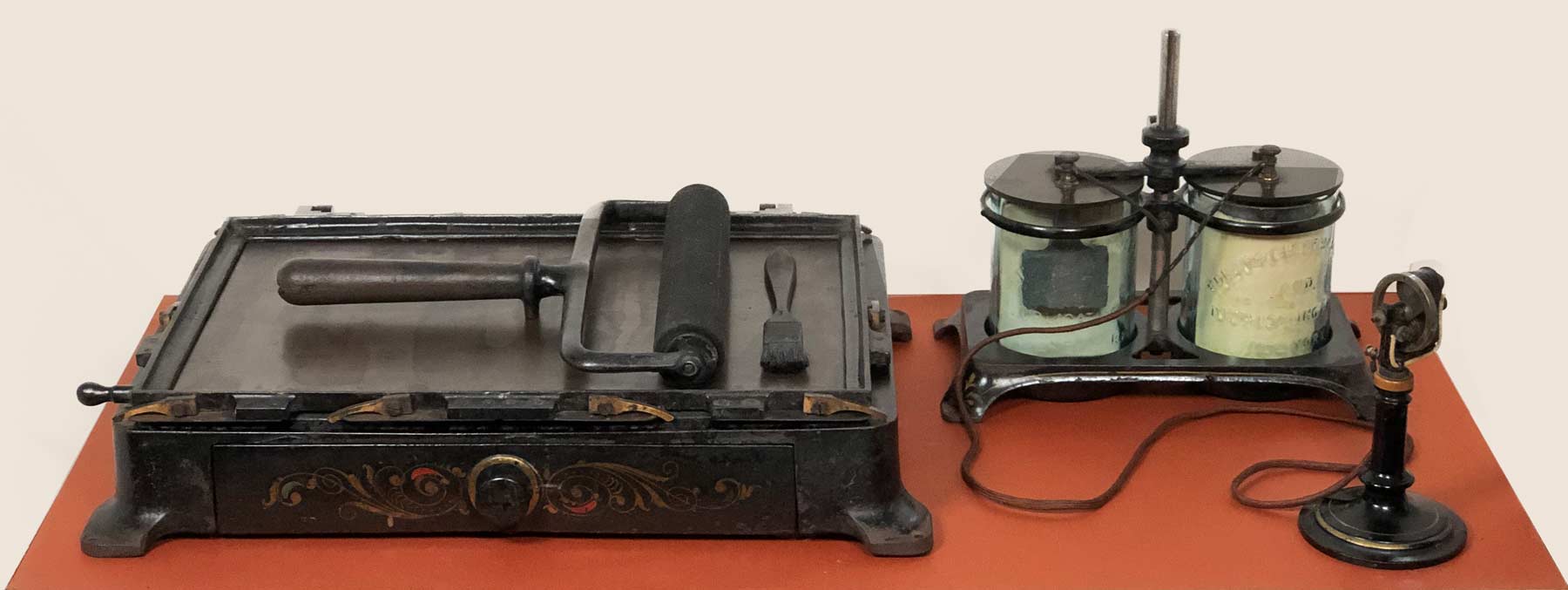
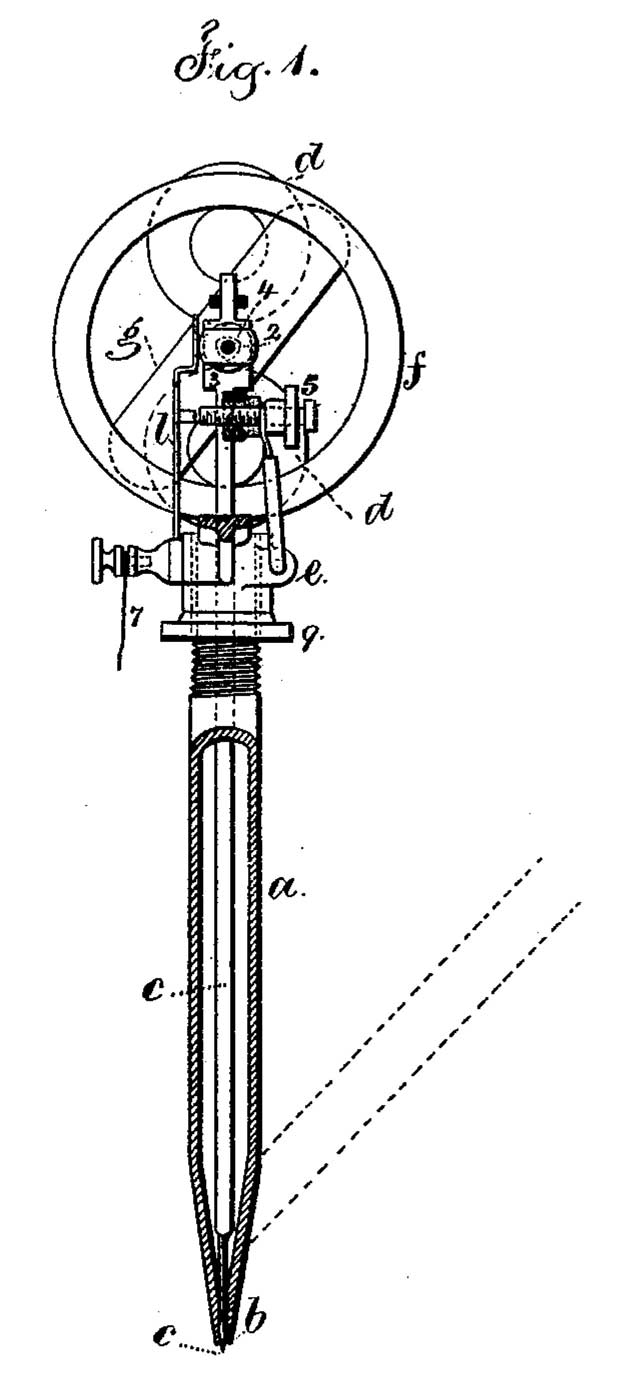
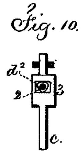
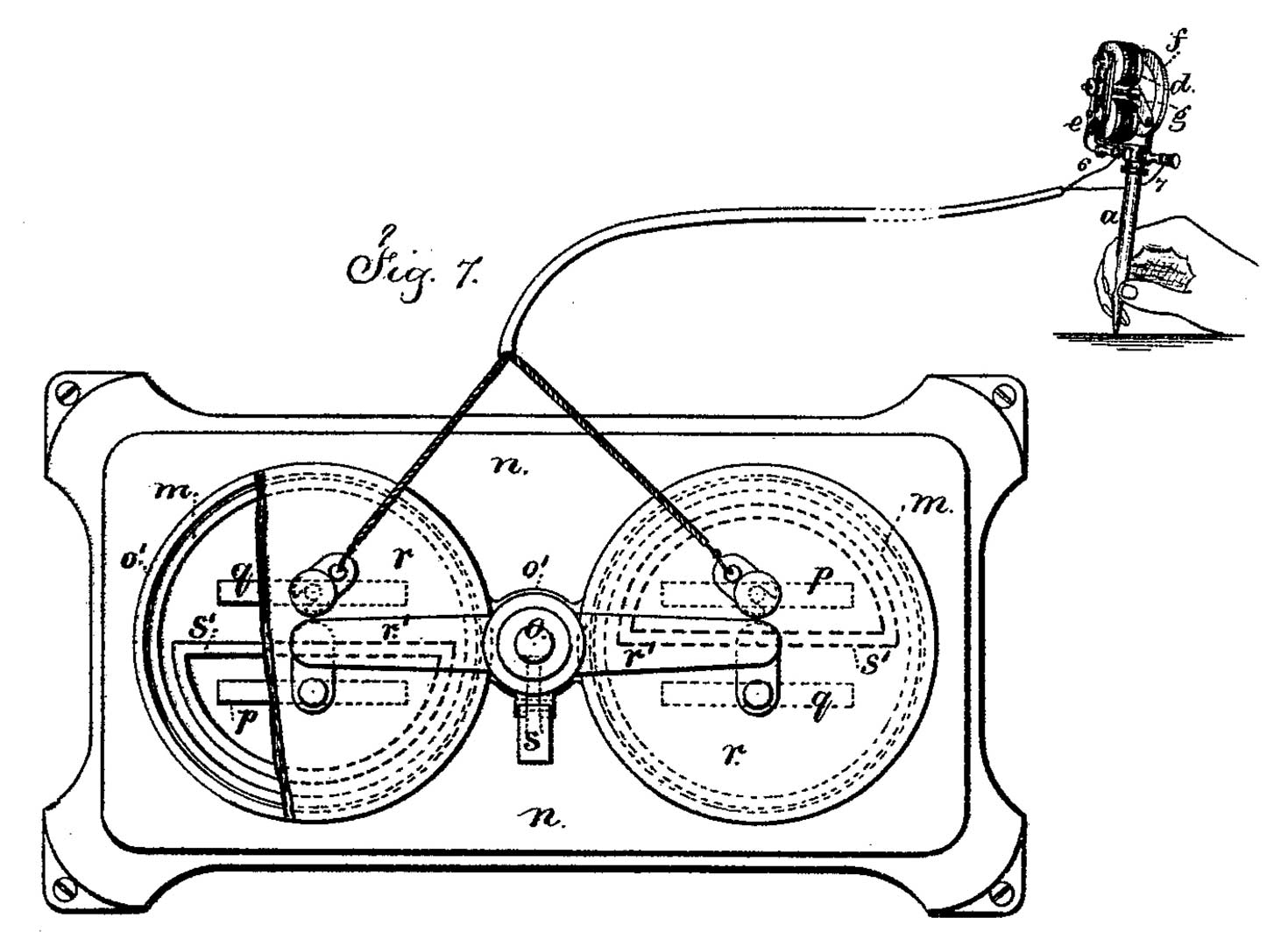
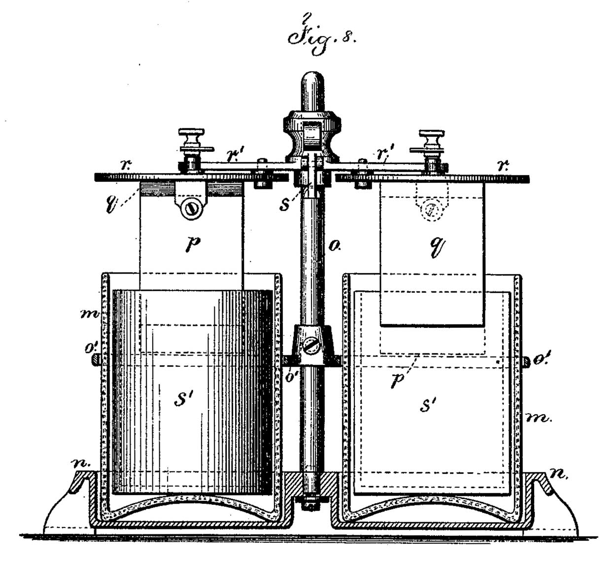
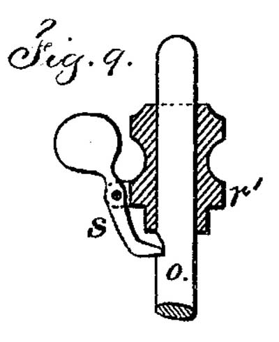
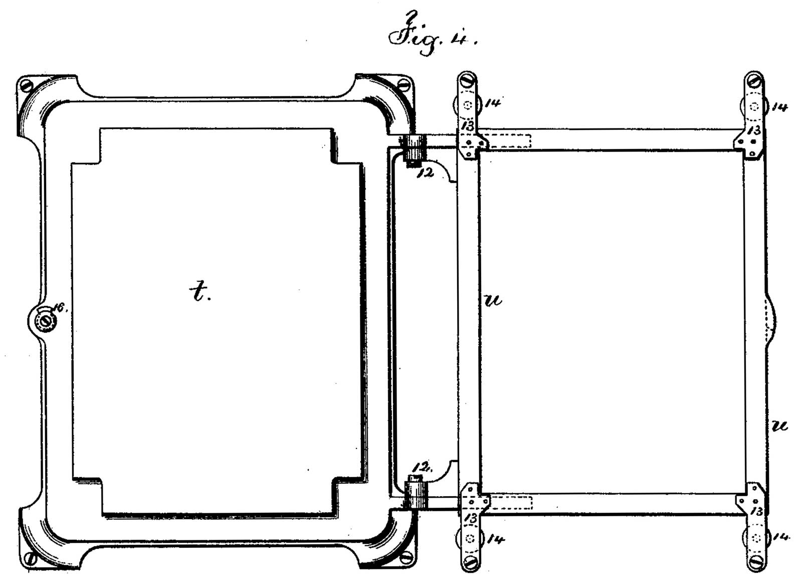
In the drawing, Figure 1 is a vertical section of the pen or stylus, in a form that I have discovered to be very convenient in use. Fig. 2 is a side view of the actuating-magnets. Fig. 3 is a section of the press. Fig. 4 is a plan of the same, as open. Fig. 5 is a section of the paper-holding clamp. Fig. 6 is a section of the pen-holding stand in smaller size than the pen Fig. 1. Fig. 7 is a plan of the battery, illustrating, also, the flexible connection to the distant pen as in use. Fig. 8 is an elevation of the battery, partially in section; and Fig. 9 is a section of the pole-supporting catch of the battery.
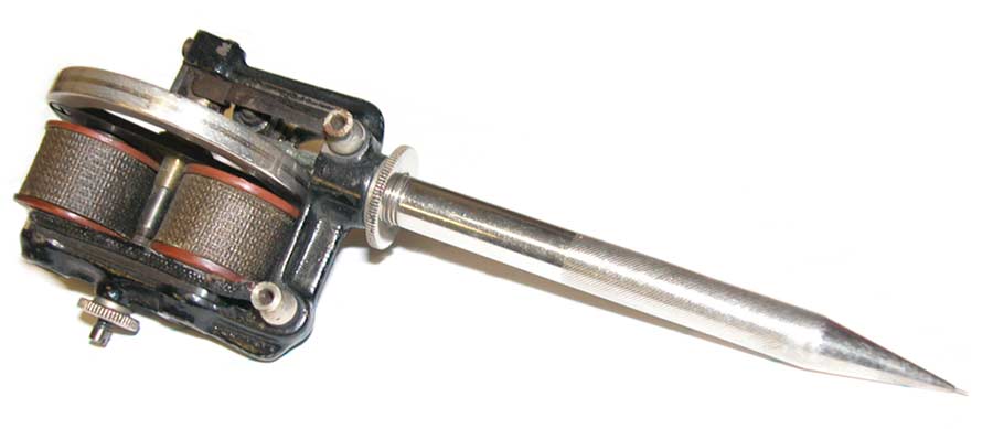
The pen which I make use of consists of a tube, a, tapering to a small point, b, and a needle, c, within that tube, which needle is reciprocated with great rapidity; and when the needle-point c is projected it is sufficiently long to reach through the paper upon which the tube of the pen rests, and when retracted the needle is drawn within the tube, so that the small end thereof is free to be moved from place to place.
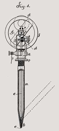
Fig. 1
The electric pen
|
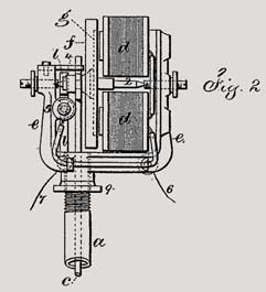
Fig. 2
Electric pen motor
|
The great rapidity in the movement of the needle-point produces the punctures in the paper sufficiently close together to form lines when the pen is manipulated in writing or drawing; and, as nothing is removed from the paper, its strength is not materially injured by the punctures or perforations; and it will be apparent that any suitable device may be employed for reciprocating the perforating needle; and as I have invented numerous devices for which I contemplate applying for Letters Patent hereafter, I have only shown herein the device which I prefer to use, viz: an electro-magnet and revolving-armature fly-wheel.
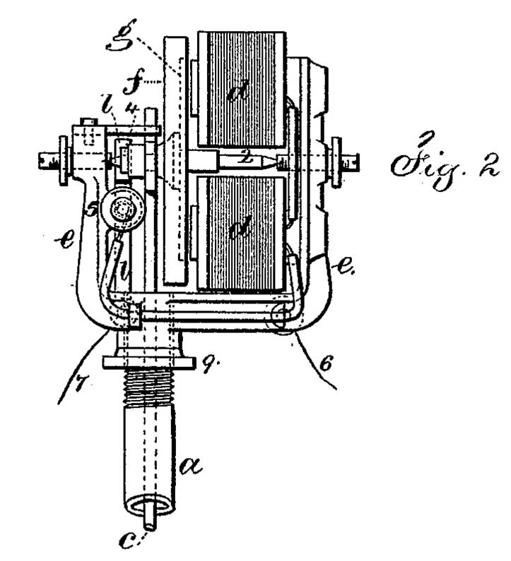
The electro-magnet d is upon the frame e that supports the axis 2 of the fly-wheel f, and this fly-wheel is connected with the armature g. Upon the axis 2 there is an eccentric or a cam, with one or more arms acting upon the stock 3 at the upper end of the needle bar. It is preferable to employ a three-pointed cam, d2, as seen in Fig. 10, upon the axis 2, so as to give three up-and-down motions to the needle-point each revolution of the axis 2.
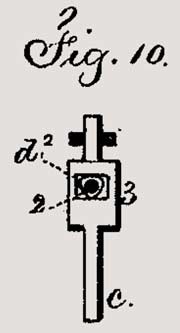
Fig. 10
Needle cam
(not to scale) |
The commutator or circuit-closer to the electromagnets is composed of the spring l, acted upon by the notched or flattened disk 4 to open and close the circuit through the screw 5, and thus actuate the electro-magnetic motor in the usual manner.
The wires 6 and 7 lead to the battery shown in Figs. 7 and 8, in which the glass cells m are in a metal stand, n, held by the standard o and ring o'. The carbon-pole p and zinc-pole q are connected with the cover r and cross-bar r', that are fitted to be raised or lowered upon the standard o, and when raised out of use, as in Fig. 8, the parts are held up by the latch s passing into a notch in the standard o, as in Figs. 8 and 9. The porous cups s' in the cells m are nearly half-cylinders, as shown. This construction of battery is very convenient for this autographic pen, because it occupies but little space and is easily transported and brought into or put out of action. The liquids preferably employed in the battery are bichromate of potash and sulphuric acid.
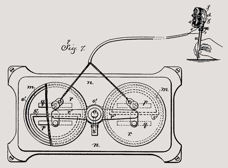
Fig. 7
Battery stand and flexible connection to pen
|
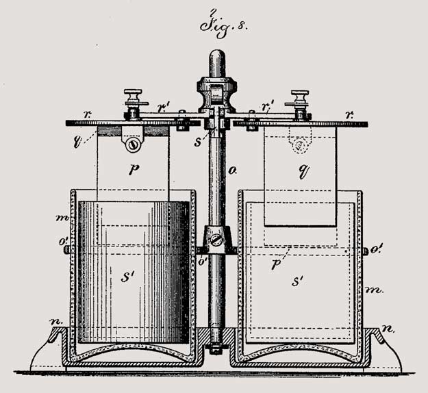
Fig. 8
Battery jars, porous cups, zinc and carbon poles
|
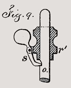
Fig. 9
Pole-supporting latch
|
The tube of the pen screws into the frame e, and it is provided with a set-nut, 9, by means of which it can be clamped after the tube has been adjusted, so as to allow the needle to be drawn into the tube and projected by the motor as aforesaid.
A stand, l', Fig. 6, is provided with a hole at the upper end, of a size to receive the tube of the pen and support the same, and protect the point from injury when entered within such stand. The conductor from the pen to the battery must be flexible, so as to allow the pen to be easily moved about in performing the writing.
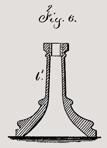
Fig. 6
Pen stand
|
The mode of printing from the perforated sheet is to fill the holes with ink by means of a roller applied to the right side of the perforated sheet; and then when said ink is well worked into the holes to place beneath such perforated sheet the paper upon which the impression is to be made, and then pass over the perforated sheet a roller that presses the ink through the perforations to the surface of the sheet below.
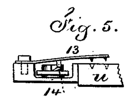
As a convenient means for doing this printing, I make use of the bed t, to which the frame u is hinged at 12, and at the corners of this frame u are the spring-plates 13, with holding-points; and these spring-plates are raised from the surface of the frame by turning the cam-buttons 14, so that the perforated sheet can be placed between the frame and these clamping-springs; and then the cam-buttons 14, being turned the other way, allow the springs to catch and firmly hold the corners of the perforated sheet. A sheet of paper is now laid down upon the bed t, the frame u turned over upon it and secured by the clamping-button 16 being turned over the edge of this frame u. A roller, covered with felt or other similar material, and having ink upon its surface, is now rolled over the perforated sheet until all the holes are filled and an impression made by the ink through such holes upon the surface of the sheet below. The hinged frame holding the perforated sheet may be lifted for inspecting the impression, and closed down again if the impression is defective at any part. After the holes are filled the impressions upon other sheets can be made in succession very rapidly, and a small quantity of ink is added from time to time. Printer's ink, thinned out with castor oil, may be employed, or aniline colors may be used, mixed with glycerine and molasses.
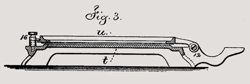
Fig. 3
Side view of the press |
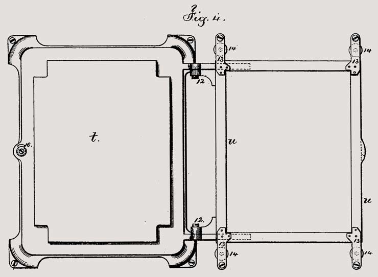
Fig. 4
Press in the open position
|
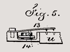
Fig. 5
Paper-holding clamp
|
Various forms of electro-magnetic motors may be employed to revolve the shaft that reciprocates the puncturing-needle, and the movement of a vibrating armature might be transferred directly to the needle, if desired.
It is generally preferable to have the perforating-needle perpendicular to the paper; and, for convenience in holding the same, there may be a handle connected with the pen-tube a, and occupying an inclined position, as indicated by the dotted lines, Fig. 1.
I claim as of my invention--
1. The portable perforating instrument for writing or drawing, composed of a tapering tubular stock, adapted to be held and moved by hand, and provided with a perforating-needle and its reciprocating mechanism, substantially as specified.
2. The method herein specified of printing in permanent semi-fluid ink by puncturing a sheet of paper, or similar material, with numerous small holes, filling such holes with a semi-liquid ink, and pressing the same upon the surface to be printed, substantially as set forth.
3. The swinging frame u and paper-holding clamps 13, in combination with the bed t, for receiving and holding the sheet of perforated paper, and the sheet to be printed, substantially as set forth.
4. The combination with the revolving magnetic motor, pen-holder a, and puncturing-needle c, of the cam d2, having three or more points, substantially as set forth.
5. The combination, with the portable hand-perforating instrument having an electro-magnetic motor, of a flexible conductor and a battery, substantially as set forth.
6. The portable galvanic battery composed of cells in a stand, with a pole-supporting rod, latch, and cross-head, in combination with flexible conductors, a magnetic motor, and a perforating-pen, substantially as set forth.
Signed by me this 7th day of March, A.D. 1876.
THOS. A. EDISON
Witnesses:
Geo. T. Pinckney,
Chas. H. Smith
|